The ballast resister is relevant to the COIL not the points.
TX-TG Gemini coils use a ballast resistor so no matter what you use to replace the points it still needs a ballast resister if you use an original coil. RB Gemini didn't have an external ballast resister and from what I see, there is only one supply wire to the (+) terminal on the coil so, it must be 12 volts, ie non resisted wiring.
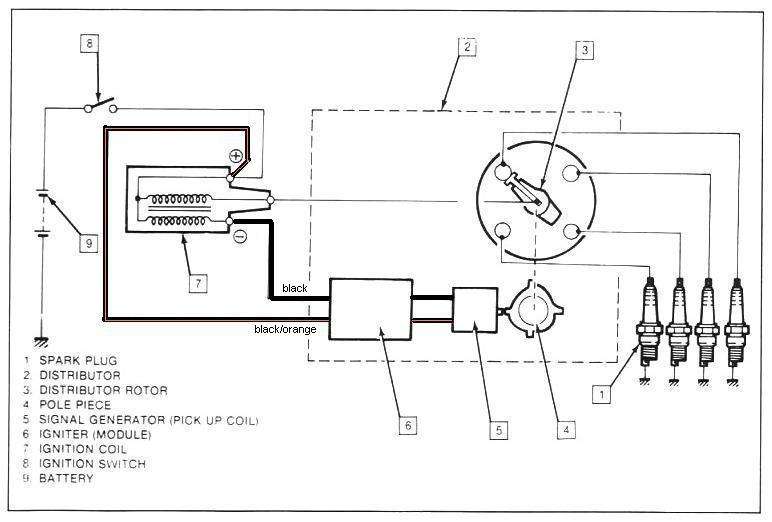
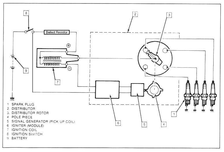
Wire the dissy as per the diagrams.
Using a coil that should have a ballast resistor:
 Using a coil that should not have a ballast resistor:

Back to resisted wiring:
What was the coil like that was on the Jackaroo? Was there a ballast resister at all? In it's original application, did it have two wires going from the main wiring loom to the (+) terminal of the coil? Have alook at a Holden EH, HT, HQ, LJ Torana, LX Torana... in fact EVERY Holden built from EH in 1964 to the HZ uses a two wire resisted coil system. They ALL have a ballast resistor, but, you won't see it.
There are two wires in the loom supplying voltage to the coil. One is a standard copper wire and it supplies 12 volts ONLY while the ignition switch is in the START position. The second wire is diffferent, it's a nickel wire and it fells a bit springy. It is a resisted wire and it supplies about 7-8 volts to the coil. That wire is the supply wire used when the switch is in the ON position.
Holden chose this two wire method instead of using a ceramic type ballast resistor as they used in the RWD Gemini.
Just because the coil wiring in a vehicle doesn't seem at first glance to be running a resistor, you have to double check the wiring leading to the coil (+) terminal.