Thanks
I have my finger in a few pies with this project at the moment. Getting ahead of myself I think!
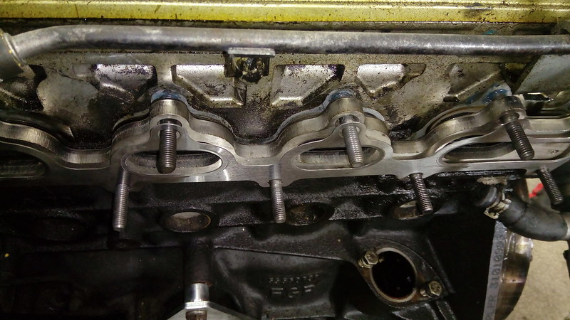
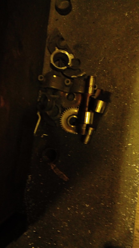
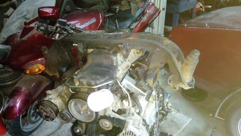
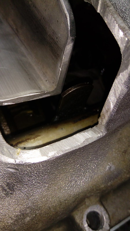
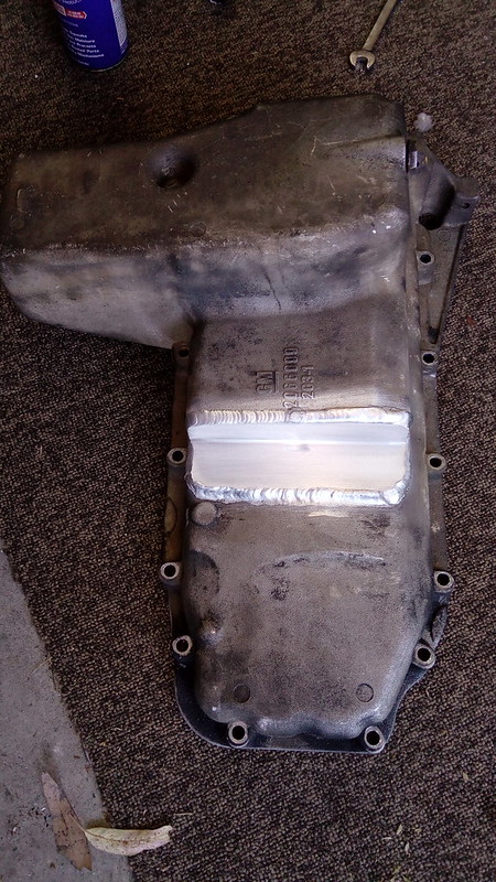
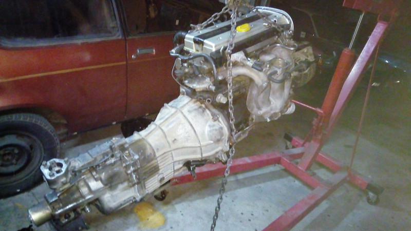
So it turns out getting a crank girdle for a Z20 is a bit harder or more expensive than expected. The C24SE Rodeo at Pick N Payless is long gone and they have a C22NE Rodeo now but the C22NE doesn't have a girdle. Then any bastard with a C24SE parts engine isn't willing to pull the girdle out so I went to plan B! Plan B involved cutting up an EB Falcon steering rack tie rod and jamming it between the bolt holes above/below, whatever, the balance shafts. This was then sent out to get TIG welded on, for free of course. When it comes back I'll cut the balance shafts off, somehow, drop saw, 9" grinder, gas axe, C4!
 IMG_20190807_134117
 by
Justin Sherwood, on Flickr
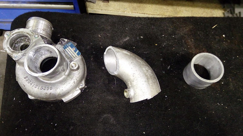
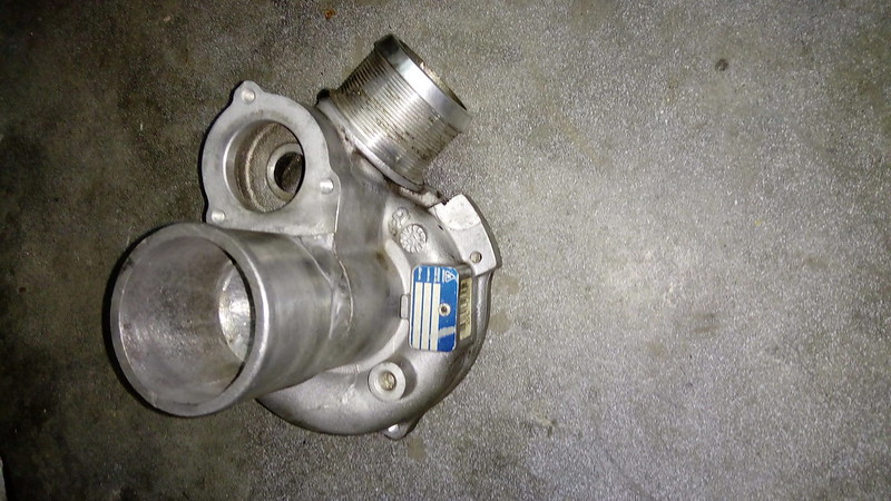
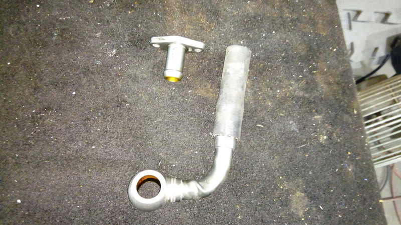
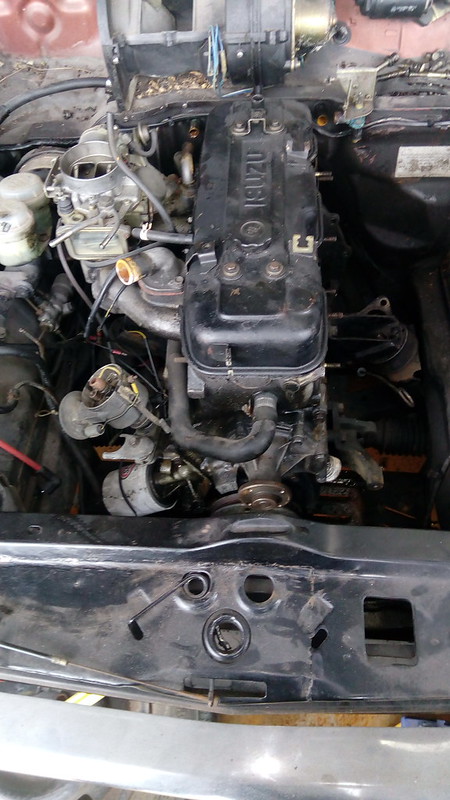
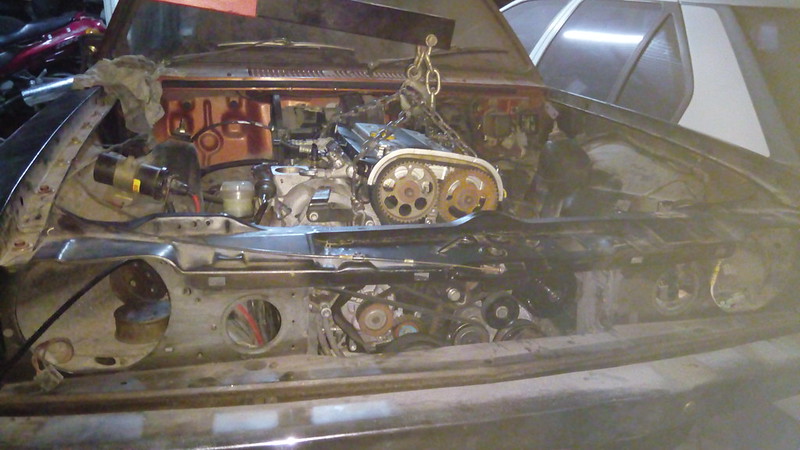
The turbo plumbing is all sorted for now. The oil drain is done and I picked up some silicon hoses to cut up to use the factory inlet crossover pipe.
 IMG_20190809_214053
 by
Justin Sherwood, on Flickr
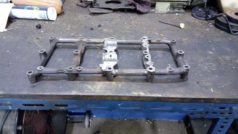
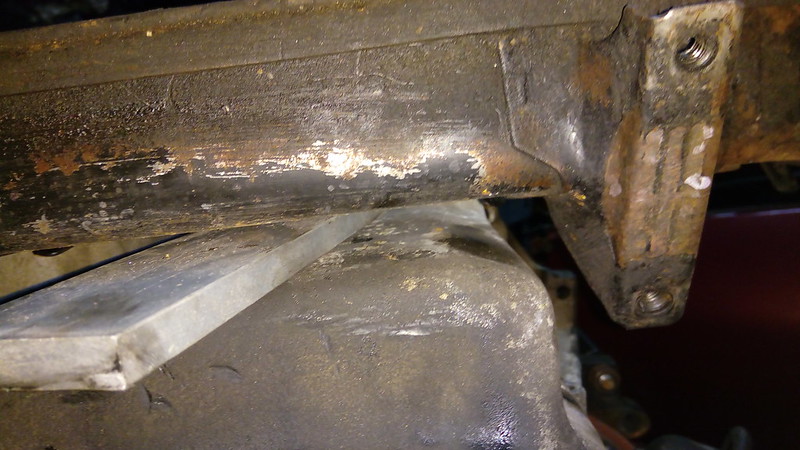
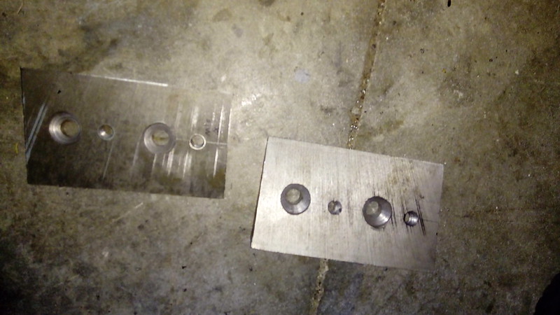
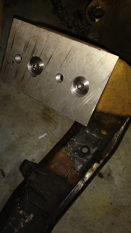
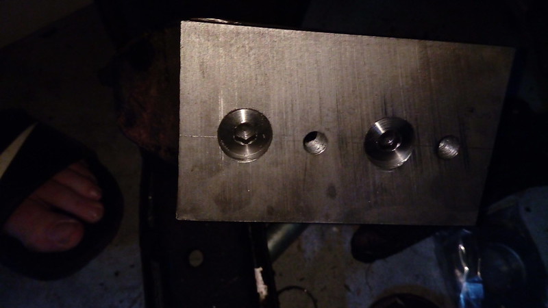
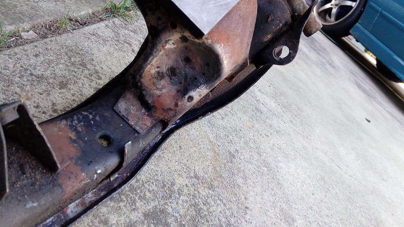
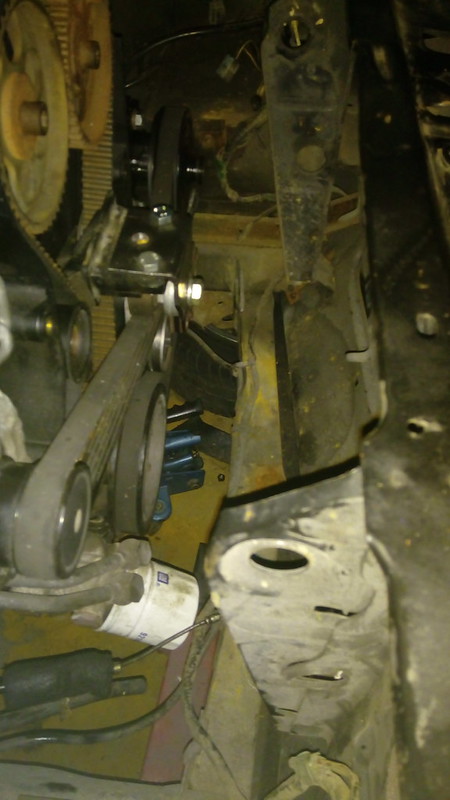
Ever wondered what the difference between the petrol and diesel cross members are. 50mm further forward and 12 degrees steeper! I still needed to move the mounting point of the engine another 30mm forward and compensate for diesels spastic 12 degree difference. So a 75 x 25 flat bar was cut up. First I cut it at work with the drop saw to 130mm long, an hour later of noise, sparks and tripping the saw, thats what I had. Next thing was to have it cut down the guts at 12 degrees. Sent it out to get cut! Bugger trying to use the drop saw for that!
 IMG_20190809_141744
 by
Justin Sherwood, on Flickr
The plan is to bolt the wedges to the cross member and bolt the rubber mounts to the wedges 30mm forward.
I could have just put a big lump of steel from a petrol crossmember to cover the 80mm or made some custom bracket off the cross member but a big lump of steel would start putting torque on the mount bolts which I thought wasn't good. Couldn't be bothered making a custom bracket! An added advantage of the wedges is there is a small amount of adjustabilility with them like up, down, side to side and angle of the dangle. In theory.
 IMG_20190809_214010
 by
Justin Sherwood, on Flickr
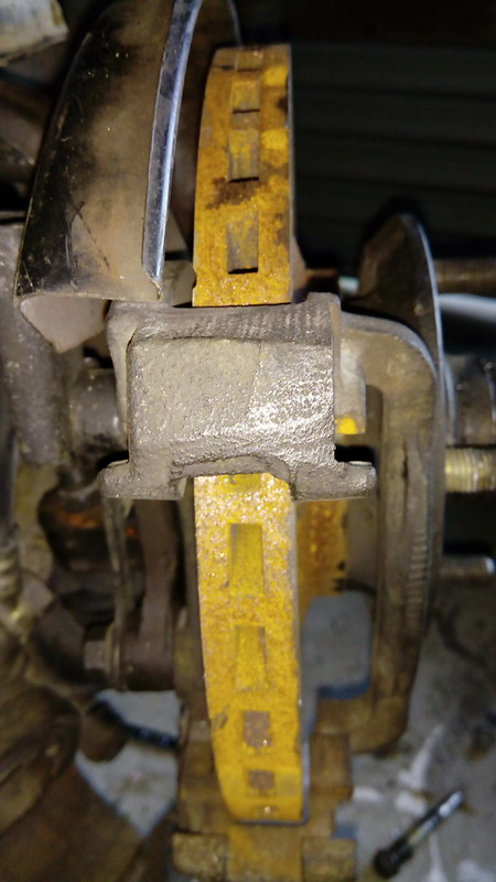
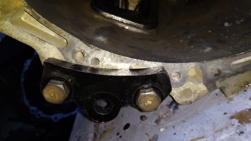
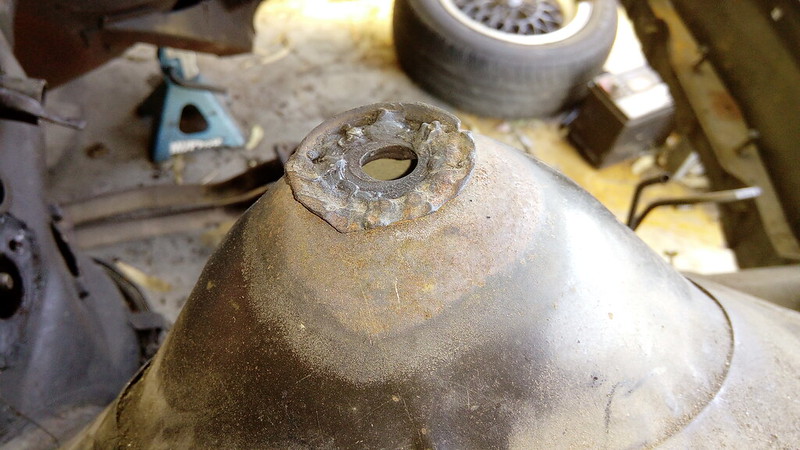
Years ago I picked up a set of turbo Piazza brakes, front and rear, or so I thought. When I went to fit them to my TG I found the calipers were for the non turbo 230mm rotors not 250mm. To make them fit I had the rotors cut down to 230mm. This is dodgy as the pads hung over the innner diameter edge a couple of mm but it worked.
 IMG_20190804_163252
 by
Justin Sherwood, on Flickr
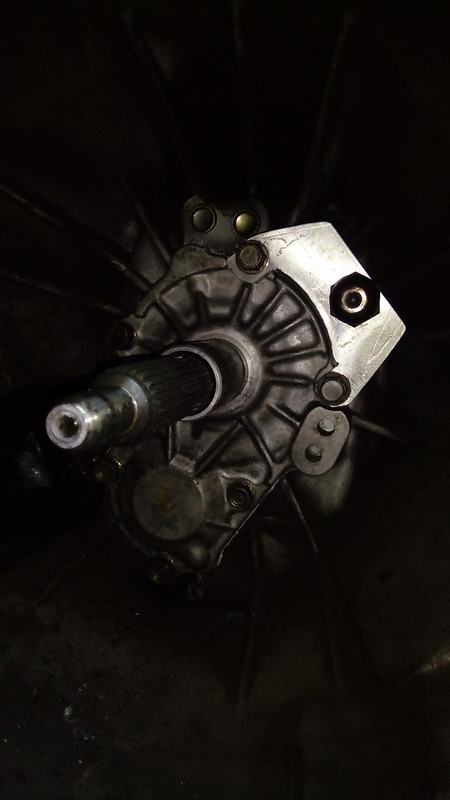
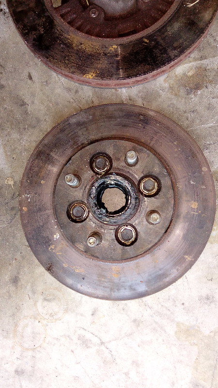
Recently I picked up some turbo rotors and calipers so the plan is to pull the Piazza stub axles off the TG and convert Gemini stub axles to fit the Piazza calipers then fit them back on the TG leaving all turbo Piazza stuff for the coupe.
 IMG_20190804_163307
 by
Justin Sherwood, on Flickr
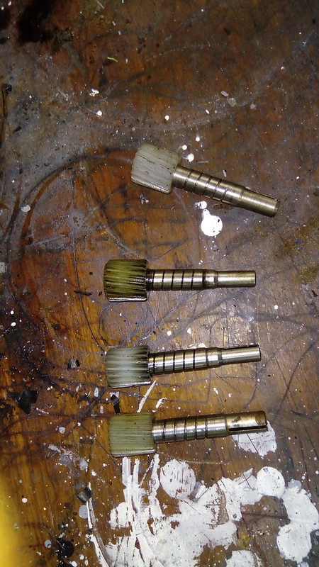
A long time ago I read that all you had to do to convert Gemini stub axles was to drill the threads out and fit washers in between the caliper and axle. Where that came from I don't know but it's bulls*#t! The problem is the Gemini stub axles aren't machined flat on the side you mount the Piazza calipers, its just raw casting. Another thing is you can only convert late model single piece axles as when you machine enough off the early axles with seperate caliper mounting bracket to fit there won't be enough material left.
 IMG_20190804_171344
 by
Justin Sherwood, on Flickr
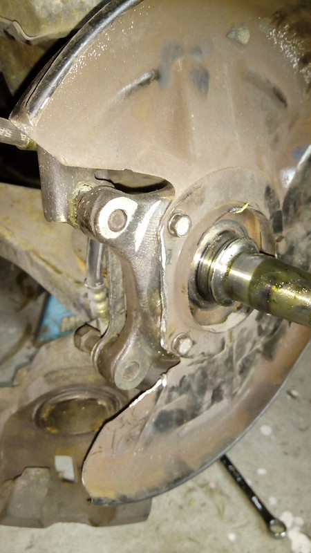
I thought this wasn't a problem as I should have a pair of late axles that came off the TG when the Piazza axles went on. Nope! I only found one. The other must have grown legs. So I'm currently sourcing another.
 IMG_20190804_171411
 by
Justin Sherwood, on Flickr
The first thing was to get the Gemini axle in the lathe and turn the casting off. I only took just enough off so it was flat. The second was to drill the threads out to 10mm. This was all easier said than done as these axles are bloody hard material. The lathe work was really slow and the drilling needed the drill press on dead slow with lots of lube. They fit pretty well though and put some pics up later.
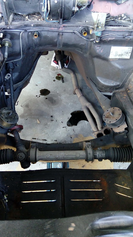
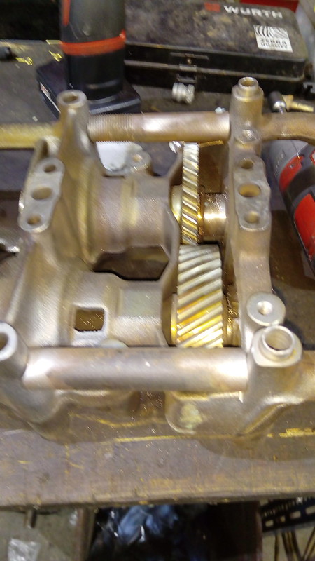
The other bright idea I had was to fit power steering to the coupe. Years ago I acquired a Piazza power steering rack and Jackaroo power steering pump with bracket to fit to the TG but that never happened as there was too much pissing about to make it fit and I didn't have the gear to do it. So I thought why not fit it to the coupe.
The first problem with the Piazza rack is the mounting brackets are wider than the Gemini ones. My solution was to weld up the holes in the brackets and redrill the to suit the Gemini cross member.
 IMG_20190809_214043
 by
Justin Sherwood, on Flickr
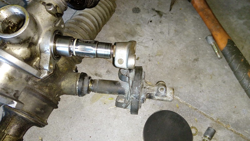
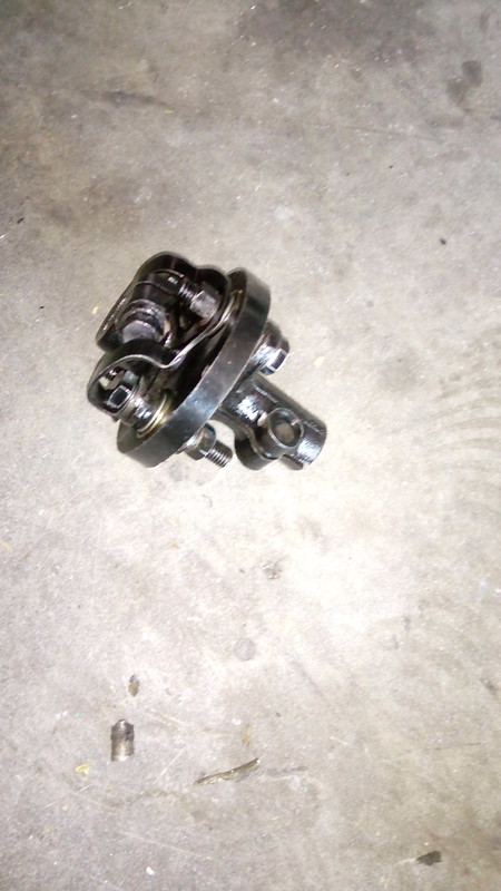
The second problem with the Piazza rack is that it's 20mm longer on the passenger side from the pinion. You could fit it as is but you could run out of thread on the tie rods when you align things. So I pulled it all apart and figured out how to take 20mm out of it.
 IMG_20190807_090607
 by
Justin Sherwood, on Flickr
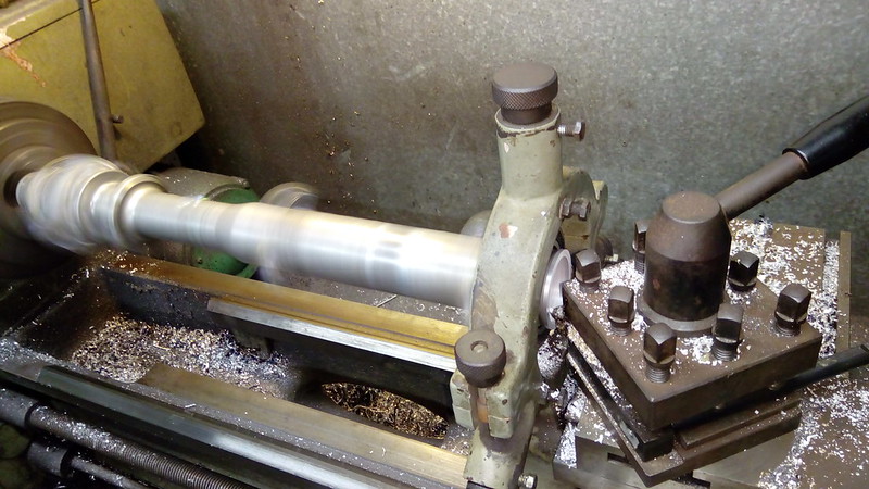
The first thing was to shorten the housing but getting it into the lathe was a trick with the equipment I have. I put the pinion side in in the chuck and held the other end with the pointy, spinny dodad thingy on the other end then turned the ridges on the end down to 50mm diameter. The first ridge measured at 50.5mm and the second at 51.5mm so no biggy.
 IMG_20190807_090810
 by
Justin Sherwood, on Flickr
Put a 6010 bearing on the end of the housing and mounted the bearing in the 3 pointed clamp thingy. This left the end open to be machined. Bored the end plug ridge in 20mm, machined 20mm off the end and cut a new circlip groove.
 IMG_20190807_092221
 by
Justin Sherwood, on Flickr
 IMG_20190807_102255
 by
Justin Sherwood, on Flickr
Now that the end plug/rack bearing sits in further it now covers one of the fluid ports so I machined a groove around it to line up with the port then cut grooves from there to the end to allow the fluid into the hydraulic cylinder.
 IMG_20190807_110658
 by
Justin Sherwood, on Flickr
 IMG_20190807_112509
 by
Justin Sherwood, on Flickr
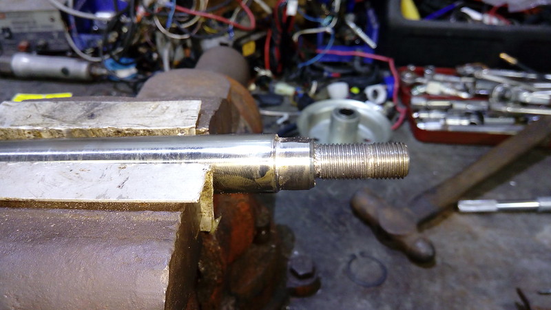
Next thing was to shorten the rack. Relatively simple job really in the lathe. Just remade the shape of it 20mm further in then cut the 14mm thread.
 IMG_20190808_095642
 by
Justin Sherwood, on Flickr
 IMG_20190808_104415
 by
Justin Sherwood, on Flickr
 IMG_20190808_105244
 by
Justin Sherwood, on Flickr
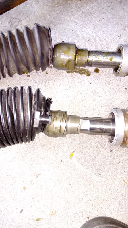
Put it together and compared it to a Gemini rack. You'll notice the rack is still longer than the Gemini one but the Piazza tie rods are shorter. The whole lot is within 1 or 2mm of the Gemini rack.
 IMG_20190809_150124
 by
Justin Sherwood, on Flickr
 IMG_20190809_150302
 by
Justin Sherwood, on Flickr
 IMG_20190809_150137
 by
Justin Sherwood, on Flickr
 IMG_20190809_150151
 by
Justin Sherwood, on Flickr
 IMG_20190809_150158
 by
Justin Sherwood, on Flickr
 IMG_20190809_150212
 by
Justin Sherwood, on Flickr
 IMG_20190809_150237
 by
Justin Sherwood, on Flickr
The third problem with the Piazza rack is the pinion. It has a spline connection to the column where the the Gemini is one piece to the rag joint. The spline is the same on the end of the Gemini steering column and so my initial thought was to use 2 of the spline bits that join the column to the rag joint but way too long. Then I thought a universal coupling or a rag joint from something else. I could make something up but then it would need to be scrutinized by an engineer and replacing it if needed would be a pain. If I can say this part is from that car it makes life a lot easier. Forget about the rack shortening business, it'll look factory! Problem is the spline is not a common size in the aftermarket scene and not documented when it comes to OEM stuff. It's looking like a Toyota Liteace rag joint/coupling will fit, maybe. I'll find out, the hard way of course!
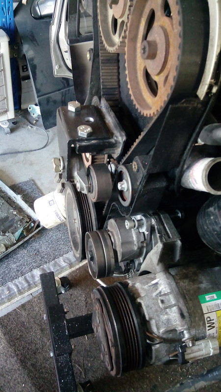
Then there is the pump to run this s*#t! I could just get something like an Astra electric pump, nah! I would have to find somewhere to mount it then and wire it. So I'm going to use the Jackaroo pump I have. It's a nice small unit and I already own it. It'll go somewhere here.
 IMG_20190809_214358
 by
Justin Sherwood, on Flickr
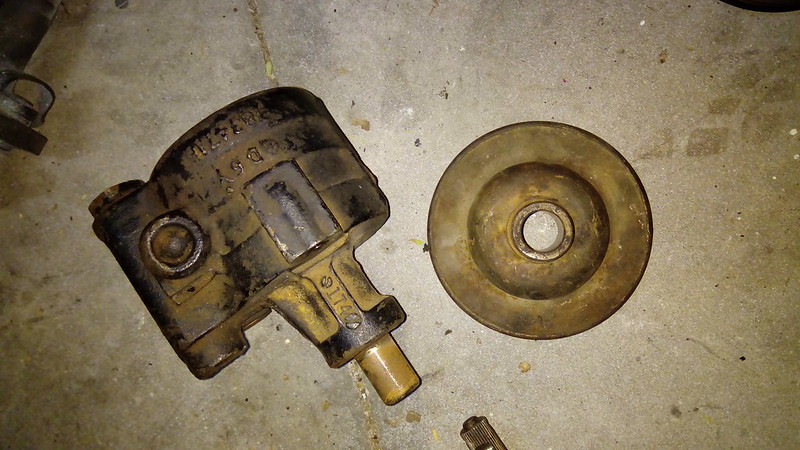
Jackaroo had a V belt setup and the Z20 has a 5pk belt so I needed a 5pk pulley on the pump.
 IMG_20190809_214145
 by
Justin Sherwood, on Flickr
I found a 6pk compressor pulley on an old compressor in this pile.
 IMG_20190810_155230
 by
Justin Sherwood, on Flickr
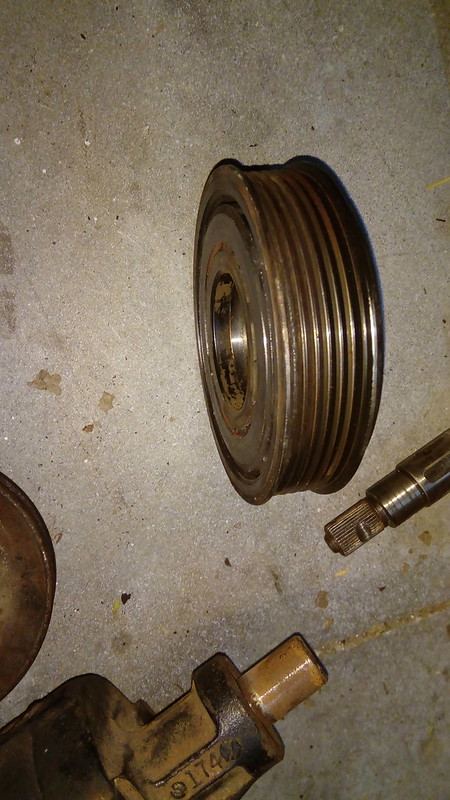 IMG_20190809_214207
 by
Justin Sherwood, on Flickr
I'll weld it on to the original V pulley something like this after I've figured out how to mount the pump.
 IMG_20190809_214234
 by
Justin Sherwood, on Flickr

 DSC_0911 (Medium) by Justin Sherwood, on Flickr
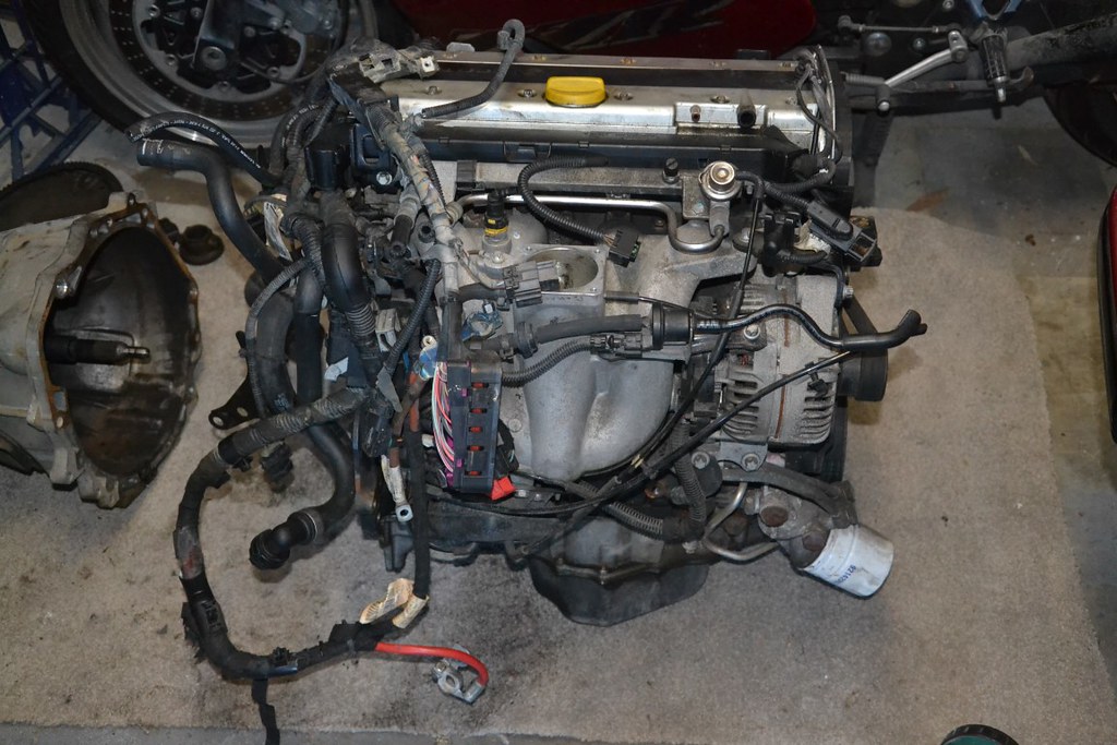 DSC_0912 (Medium) by Justin Sherwood, on Flickr
 DSC_0913 (Medium) by Justin Sherwood, on Flickr
 DSC_0914 (Medium) by Justin Sherwood, on Flickr
 DSC_0917 (Medium) by Justin Sherwood, on Flickr
 DSC_0916 (Medium) by Justin Sherwood, on Flickr
 DSC_0920 (Medium) by Justin Sherwood, on Flickr
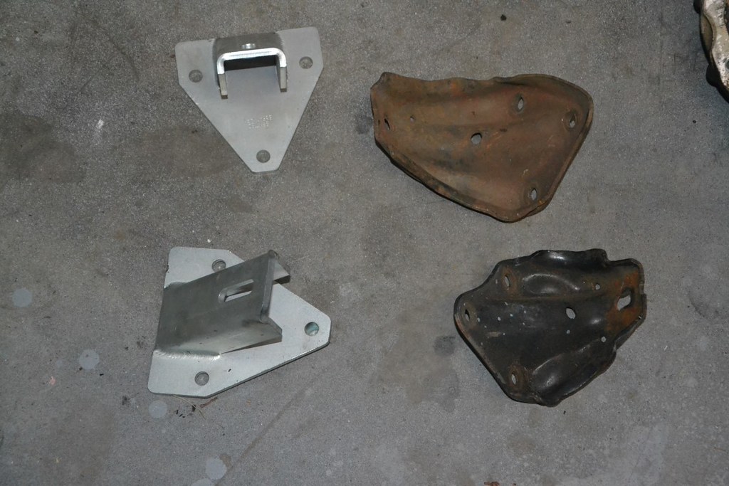 DSC_0915 (Medium) by Justin Sherwood, on Flickr
 DSC_0919 (Medium) by Justin Sherwood, on Flickr
 DSC_0918 (Medium) by Justin Sherwood, on Flickr
 DSC_0921 (Medium) by Justin Sherwood, on Flickr