So why do a conversion to a Weber 32/36?
• Performance? Slight improve over a Nikki but better fuel economy and easier to keep in tune.
• Maintenance. A 32/36 is a wonderfully simple and well made carburettor and you don’t get the spindle wear problems of the more complex and harder to service Nikki.
• Availability – plenty of these carburettors around and parts reasonably easy to come by.
A 32/36 is about the worlds easiest carburettor to rebuild and anyone can do it with a few basics tools and care in following the advice on some of the key linked sites I am suggesting below.
Helpful Places
I have put John Connolly’s jetting theory article first. An understanding of the three main fuel circuits/ systems in a carby (idle/progression, main jet, air jet) is really helpful
http://www.aircooled.net/gnrlsite/resou ... etting.htm
Dennis Hale’s article is widely referenced. It’s a good article but he starts with main jet sizing whereas I prefer to sort out the idle / progression system before the main – and he gets the DGAV meaning wrong
http://dimequarterly.tierranet.com/arti ... uning.html
This is a Link to Chris Reece’s site – the trouble shooting section of this site is the most useful bit. It looks like a lift from a Weber manual
http://www.jessies.org/~car/projects/carb/
Jetting Table – describes the factory jetting for the different Weber types. It will tell you if yours have been interchanged or whether they are factory set.
http://www.gracieland.org/cars/techtalk/weboem.html
Nice simple exploded diagram but…
http://www.gowerlee.dircon.co.uk/DGAVtype.html
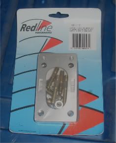
.. the Redline Weber tech section has more detailed explode diagram, parts list and idle tuning tips
http://www.redlineweber.com/html/Tech/T ... ntents.htm
Some good picks and small engine jet sizes
http://www.izook.com/tech/samurai/engin ... /weber.htm
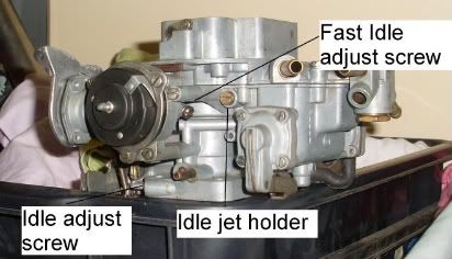
Idle adjustment and selecting an idle jet size
http://www.carburetion.com/Weber/adjust.htm
Choosing Weber
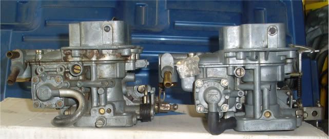
The Weber 32/36 were produced as:
• DGV - a manual choke model
• DGAV – water choke model
• DGEV – Electric choke model
• DFV – mirror version of a DGV – rarer, but some prefer it for Gemini application
The big brother is the 38 DGES and the cousin is the 34 ADM.
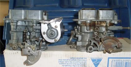
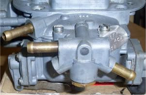
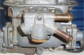
Note the 38DGES left has the extra idle tuning screw in the base.
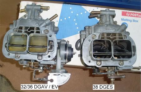
Top section of the 32/36 and 38 almost identical.
The 32/36 is a two barrel carburettor has a 32 mm barrel that operates at low speed and a 36mm barrel that manually operates at ¾ throttle. A 34 ADM operates the same way and has two 34 mm barrels. A 38 DGES has two 38 mm barrels that are synchronised to open at the same time.
The standard Nikki is a two barrel carby also but relies on vacuum / air flow as well as a mechanical link to operate the second barrel at high revs – and it often doesn’t work too well. With a Weber – put your foot down and it happens.
The 34 ADM is commonly sourced from old Ford Falcons and re jetted. I’m not a fan because the 34 ADM is an emission control carburettors while the 32/36 is a pre emission carby. There are forum members who have successfully adapted the 34 ADM carburettors.
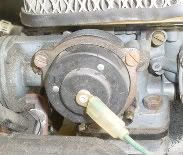
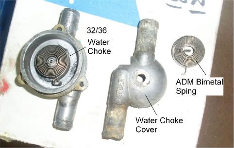
A lot of people remove the cold start choke mechanisms from DGAV and DGEV 32/36 carburettors to make the accelerator cable adaption a bit easier. I like to keep the electric choke because it works brilliantly. The DGAV water choke can be easily converted to an electric choke – more on that later.
Preparing Your Weber
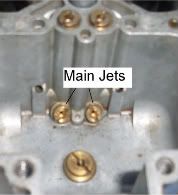
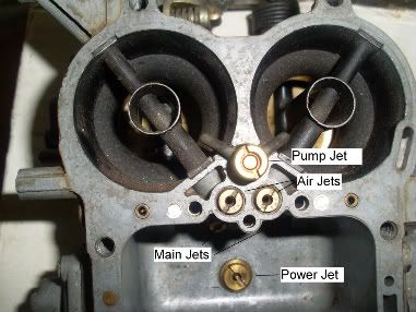
First job is to find out what you have. Remove the top cover (taking care to unclip the choke link) and check the sizes stamped on the following bits and write them down for later reference:
• Main jets
• Air correction jets
Unscrew the air correction jets and note the marking on each
• e-tube
Unscrew the idle jet holders and note the size of the:
• Idle jets
Remove and check the
• pump jet
It is highly recommended that you put a kit through the carby – replacing the needle and seat, gaskets and “O” rings.
The links above will provide an exploded view and parts list for your model. When you disassemble the 32/36 it is not advisable to remove the butterflies from the spindle as the screws are a one-time use and will tend to strip when removed. Unless the nylon spindle shaft bushes need replacing – leave it alone.
Use screw drivers that exactly fit the screw slots. If the e-tubes get stuck try to hook them out with a piece of wire after a liberal soak with WD40.
Use two trays – one for your dirty parts and one for your clean parts and don’t but the trays where your dumb mate will kick it all over the shed (bitter experience talking here).
Cleaning
A wash in clean petrol using a tooth brush is normally sufficient. Then blow through the galleries and jets with compressed air. If you have some lacquer thinners repeat the wash and you will lift off most of the stubborn black staining.
Blow out the galleries again.
Warning –
• Wear eye protection – splashing petrol in you eye is bad, thinners real bad and possibly permanently damaging.
• Work in a well ventilated area and f%#k sake don’t smoke.
• Wear gloves – OK so you will probably ignore that for petrol but seriously skin contact with thinners is bad news.
Reassemble with your new kit bits. Check the diaphragm on the power valve (in the top cover) and the diaphragm in the choke pull-off. These can be purchased separately if damaged.
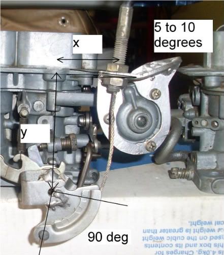
The only mildly tricky bit is setting the float level and that is described in the links.
All finished, sit back have a beer, admire your work and toast how clever you are.
More in the next instalment……